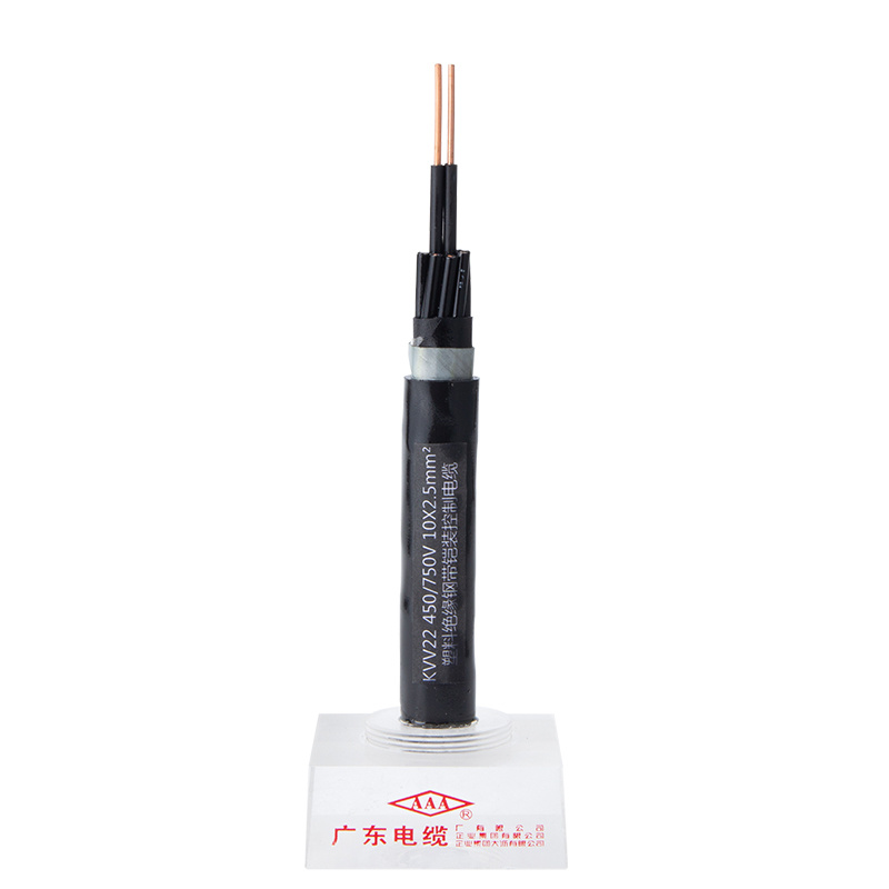
Knowing These 6 Secrets Will Make Your What Is Control Cable Look Amaz…
In other words, the hot removal capability is the responsibility of the system designer, and they should ensure the drive is stopped before hot removal occurs. Released in 2004 at the tail end of the Standard definition era, each self contained unit is a system on a chip Mega Drive clone and hosts 6 classic games on a single ROM chip. The one flaw in this plan was that sending the digital image to the Shuttle required the Tracking and Data Relay Satellite System (TDRS), which due to delays wouldn't be ready until the sixth Shuttle flight. The buttons also seemed like they could be fragile due to this being a particularly cheap (later) player (rather than being an early one of a reputable brand). Look below to see what it looks like fully assembled. If you've got a neat idea for a spatula you'd like to see here, mail it to Spatula City's manager. It’s easy to check - look for GND/SCL/SDA markings at the back of the module and see if there are pins next to them.

The Teletype busboard attaches directly to the back of the TT module. If you have a later revision Teletype (black PCB) you should not need a powered busboard. To make this easier for users, "powered busboard" expanders have been made to help - which also provide additional i2c connectors. I used a permanent ink pen to make a mark through the pi mounting holes and I didn't get them all completely lined up, so maybe it would be smarter to measure them out first. Hot-Plug Capable Hosts/Devices shall not suffer any electrical damage, or permanent electrical degradation, and shall resume compliant Tx/Rx operations after the applicable OOB operations, following the Hot-Plug Events. All the following situations shall not damage the device or host, and both the device and host shall resume normal TX/RX communication after any of the following events. Prior to removal, the Host is placed into a quiescent state (not defined here) and power is removed from the backplane connector to the Device. As you can see, I used a cable tie to add stress relief to the power cable. You may wish to add one to the HDMI cable, but it's in there pretty solid and I didn't think it needed one.
So think very carefully before you go ahead with any soldering (this is a lesson I fail to learn time and time again). This manifests primarily as no end of tinkering with inexpensive consumer IoT devices, because I am cheap and running new cabling is time consuming. In some situations with many devices, a set of "pull-up" resistors are needed to help stabilize the i2c bus. In addition to a leader device and one or more follower devices you need something that will provide power and pull-up resistors for the i2c bus. Additionally, it serves as a minijack/i2c adapter - the main use case for this is to have the ability to connect 16n faderbank, but you could also use 2 TXb to connect i2c between different rows or cases (just remember to keep the distance short). I realised when I first tried to put the two shells together that it wasn't possible to close the case. I first inspected the board and the possible corrosion issue, and checking if any components were lose.
Next we need to drill some holes so our pi board can be securely fitted to the case. Other variations attach to anisible or can sit in the back of your case (tt-busboard-jr). I won't be peeling any oranges for a day or two, I can tell you that. It can be powered by battery or a 6v power supply. I preserved the plug and play nature of the console and the LED and power button work more or less as they should, but I couldn't get the old controller wired up to the Pi Zero. This inability to read discs, I believe, is a common issue typically caused by the laser wearing out (assuming dirt has been ruled out) - surely this can come about more swiftly if using scratched discs as the laser has to do more work to track and focus. I tried detaching the ribbon cable and using deoxit there with no improvement. I have seen someone else fail to do this (on Youtube) on a device by using a soldering iron that was too hot and melted the ribbon cable, so I used my lowest wattage iron, a USB powered one that is pretty useless for most things, added some liquid flux and carefully and briefly touched the iron to each solder point.
If you liked this article and also you would like to be given more info concerning what is control cable nicely visit the webpage.